DC Buck Voltage Regulators
The low noise, compactness, and simplicity of a linear regulator — at dramatically higher efficiency. Entirely linear, so switching EMI never enters your design.
Linear regulation, past the efficiency ceiling
Polaris buck regulators eliminate the EMI effects associated with switching alternatives, simplifying circuit design and PCB layout and reducing the risk of a costly redesign. They support the most demanding low-noise applications — RF circuits, precision sensing, scientific instrumentation, low-noise imaging, medical devices — and radiation-tolerant versions suit harsh environments.
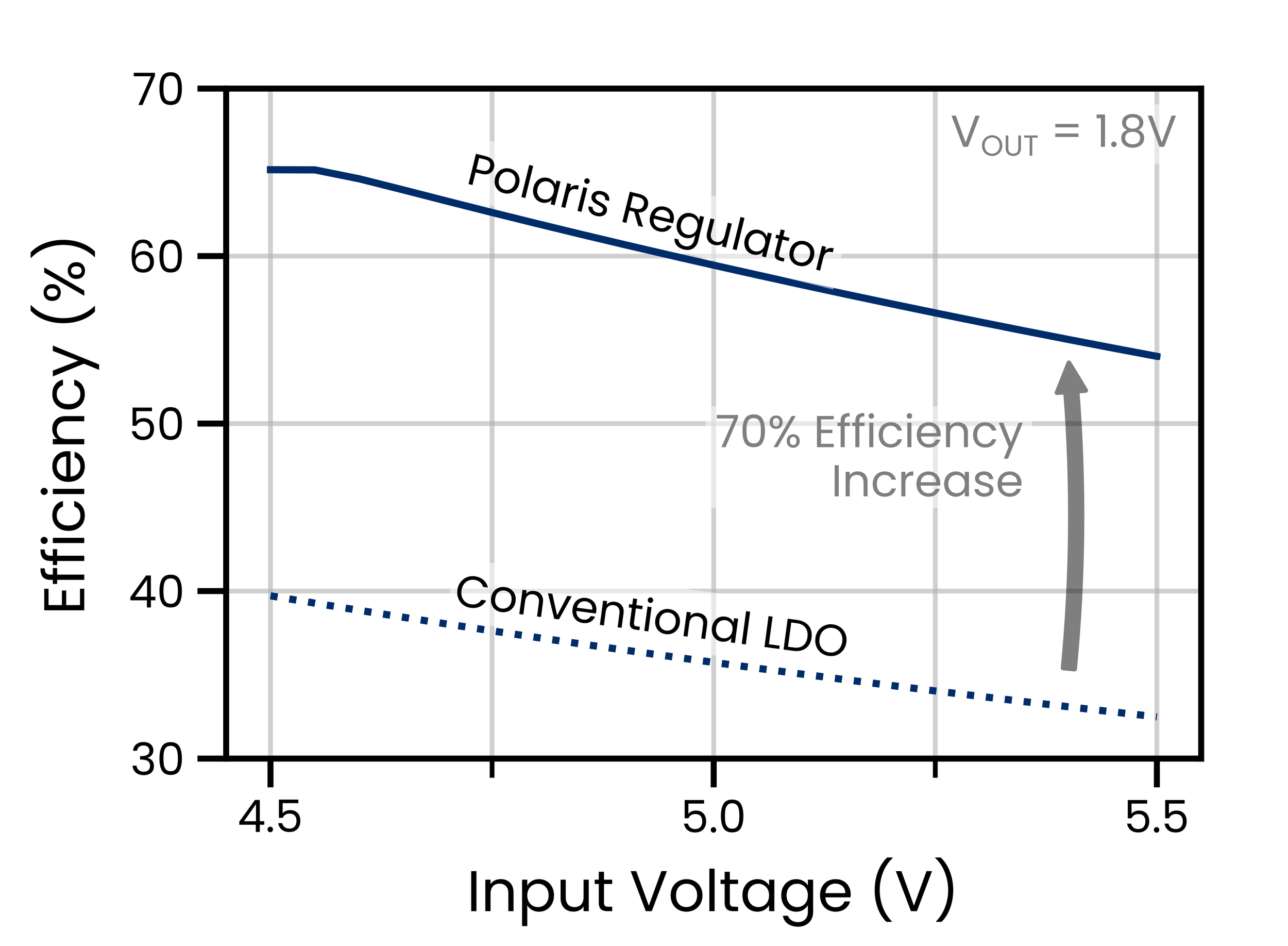
The inductorless, switching-free topology uses photons generated within proprietary optocoupler chips to unlock much higher efficiency than conventional LDOs — simplifying thermal design and cutting electrical losses without noise or footprint trade-offs.
Why engineers design these in
Smashing efficiency limits
Typically 1.2× to >2× higher efficiency than a linear regulator, depending on voltage step — expanding where linear regulation can go, slashing heat and current consumption.
Ultra-high PSRR & low noise
Proprietary photonic technology keeps the clean, ripple-free output of a linear regulator at much higher efficiency — matching the noise specs of the best available LDOs.
Minimal footprint and BoM
No inductors, only a handful of small passives. Compact QFN packages (36–49 mm², 0.8 mm profile) for space-constrained, power-integrity-critical designs.
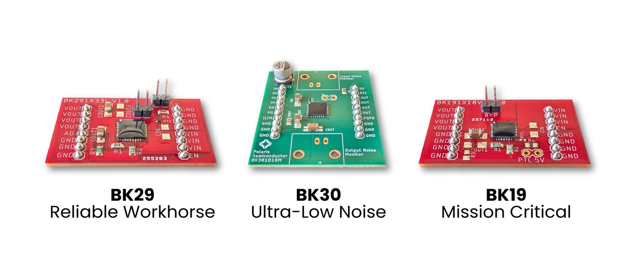
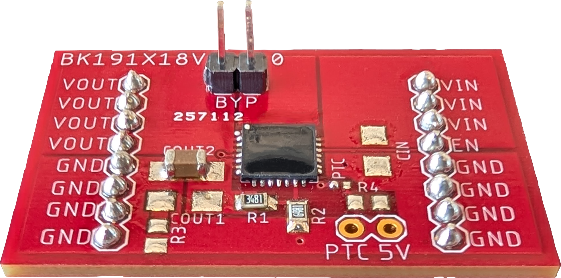
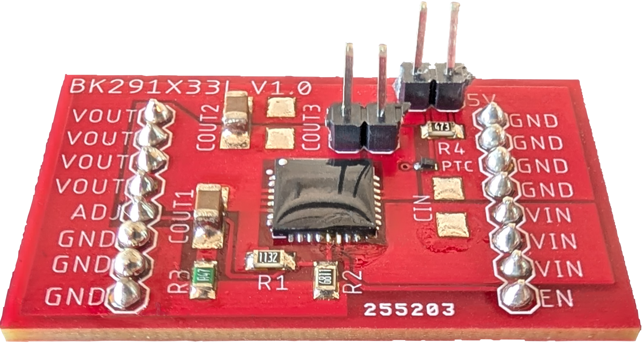
Three buck families — pick by current, noise, or radiation
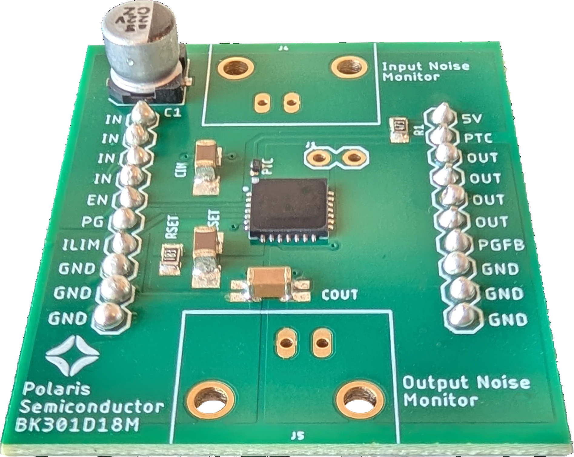
Full datasheets are available on request and every product ships on an evaluation board. Don't see your spec? We also offer custom configurations.
| Device family | Max Iout (mA) | Max Vin (V) | Min Vout (V) | PSRR @ 1 kHz | TID krad(Si) |
|---|---|---|---|---|---|
| BK19 | 900 | 20 | 1.2 | 75 dB | 200 |
| BK29 | 1000 | 26 | 1.2 | 65 dB | 200 |
| BK30 | 500 | 15 | 0 | >100 dB | 200 |
- TID ratings denote device-level radiation tolerance; the BK19 is additionally built on a QML-V radiation-hardness-assured LDO core (RH1965).
Reading a Polaris part number
Output-voltage code (buck): 18 ⇒ outputs up to 2 V · 33 ⇒ up to 4 V · 50 ⇒ up to 5 V (up to 6 V on BK301D50H). Outputs are adjustable: BK19 and BK29 devices down to 1.2 V, BK30 devices down to 0 V — see the selection table for each part's exact range.
Input-voltage range: L lowest · M medium · H high · E extended — IDs ending in V select between two ranges via board-level pin connections. Every device also runs as a conventional LDO by shorting two pins ("LDO mode").
Boost (BT) parts share the same grammar but regulate up to 5 V — see the BT29 series page for output behavior.
Choose the product family
Each family pairs a distinct LDO core with our PV-output optocouplers: BK19 for radiation tolerance on a QML-V rad-hard core (RH1965), BK29 for high current (MIC29152), BK30 for ultra-low noise (LT3045).
Select the output range
Adjustable outputs by family: BK19 covers 1.2–2 V, BK29 spans 1.2–5 V, and BK30 reaches 0–6 V. Within each range, variants are optimized for noise, output current, and radiation.
Select the input range
Match the final letter of the part ID to your rail (decoder above). Peak optocoupler-enhanced efficiency lands inside the optimized input window.
Ready to design it in?
Request evaluation samples, detailed datasheets, and SPICE models — an engineer answers, not a sales funnel.