Linear regulation, past its own limits
An Enhanced Linear Regulator is an inductorless, switching-free DC voltage regulator that co-packages a linear regulator (LDO) with patented photovoltaic-output optocouplers. The optocouplers recycle power normally dissipated in a conventional LDO, so the device keeps the low noise, small footprint, and simple bill of materials of a linear regulator while reaching efficiency approaching that of a switching regulator.
The voltage-regulator trade-off
Every electronic system needs DC voltage regulation, and for decades every regulator forced the same compromise between three things designers want at once.
Small, or switching
Switching regulators need inductors, EMI filtering, and careful layout. Linear regulators are tiny and simple — an IC and a few passives.
Efficient, or linear
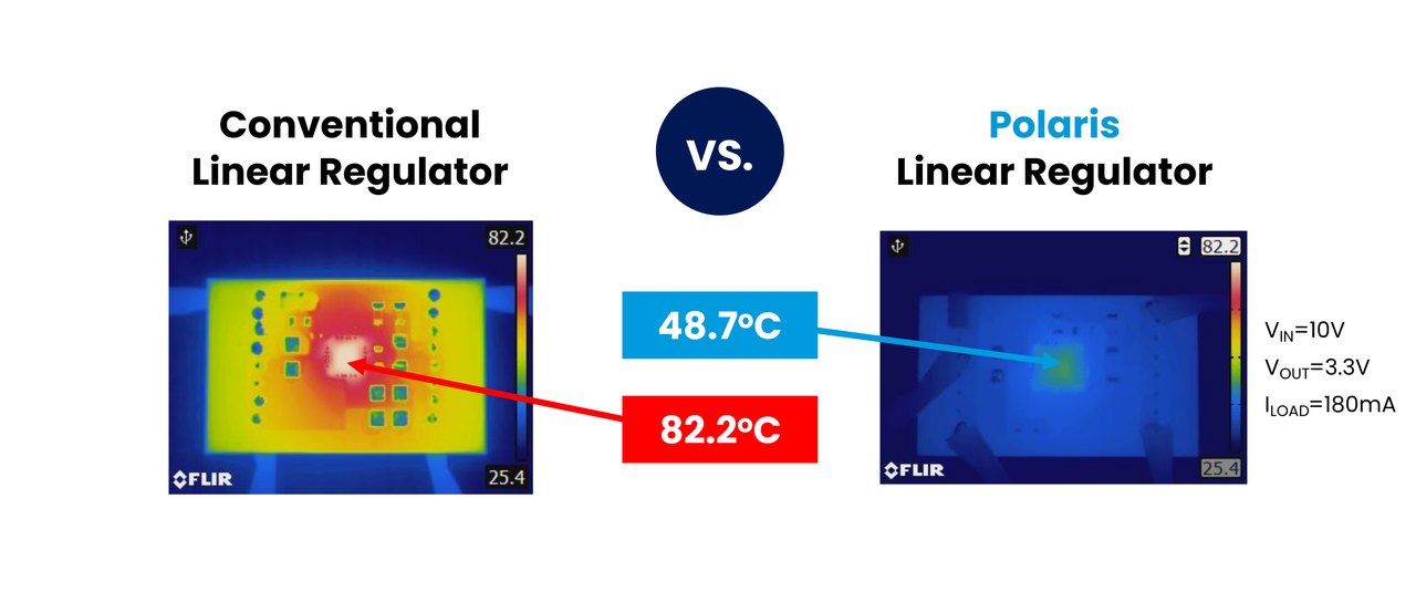
A conventional LDO burns the entire input-output voltage difference as heat. Its efficiency is capped at VOUT/VIN — the larger the step-down, the worse it gets.
Quiet, or efficient
Switching converters spray ripple and EMI across the band where RF front-ends, data converters, and precision sensors are trying to work. Linear regulators are quiet by construction.
Achieving all three simultaneously is what blocks power designers in noise-sensitive, SWaP-constrained systems. The usual workaround — a switching pre-regulator followed by an LDO — costs board area, components, and design time, and the switching noise still has to be filtered out.
Photons recycle the wasted energy
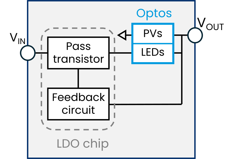
Inside an ELR, a silicon LDO is co-packaged with Polaris's proprietary photovoltaic-output optocouplers. The LDO regulates exactly as it always has — same feedback loop, same clean output. But instead of burning the dropout energy as heat, the ELR routes current through the optocoupler's LEDs, converts it to light, and converts the light back to electrical power with on-chip photovoltaic cells — power that is fed forward to the output.
Because nothing switches, there is no ripple, no EMI, and no inductor. The same mechanism also stacks voltage above the input rail, which is how Polaris built the world's first efficient switching-free boost regulator.
The terms, defined once
- Switching-free — no part of the regulator switches; regulation is entirely linear, so the output carries no switching ripple or EMI.
- PV-output optocoupler — an optocoupler whose output side is a photovoltaic cell that delivers usable electrical power, rather than a phototransistor that merely signals.
- Polaris Monolithic Optocoupler (MLOC) — a single monolithic GaAs chip integrating both the LED and the photovoltaic cell. The breakthrough section below looks inside it.
- Optocoupler-enhanced mode — operation with the optocouplers active. Every Polaris device can also run as a conventional LDO by shorting two pins ("LDO mode").
The optocoupler, reinvented as a power device
Optocouplers have relayed signals for half a century — a discrete LED facing a discrete photodetector across a gap. Polaris re-engineered the optocoupler to move power, then patented both the chip and the regulator circuits built around it.
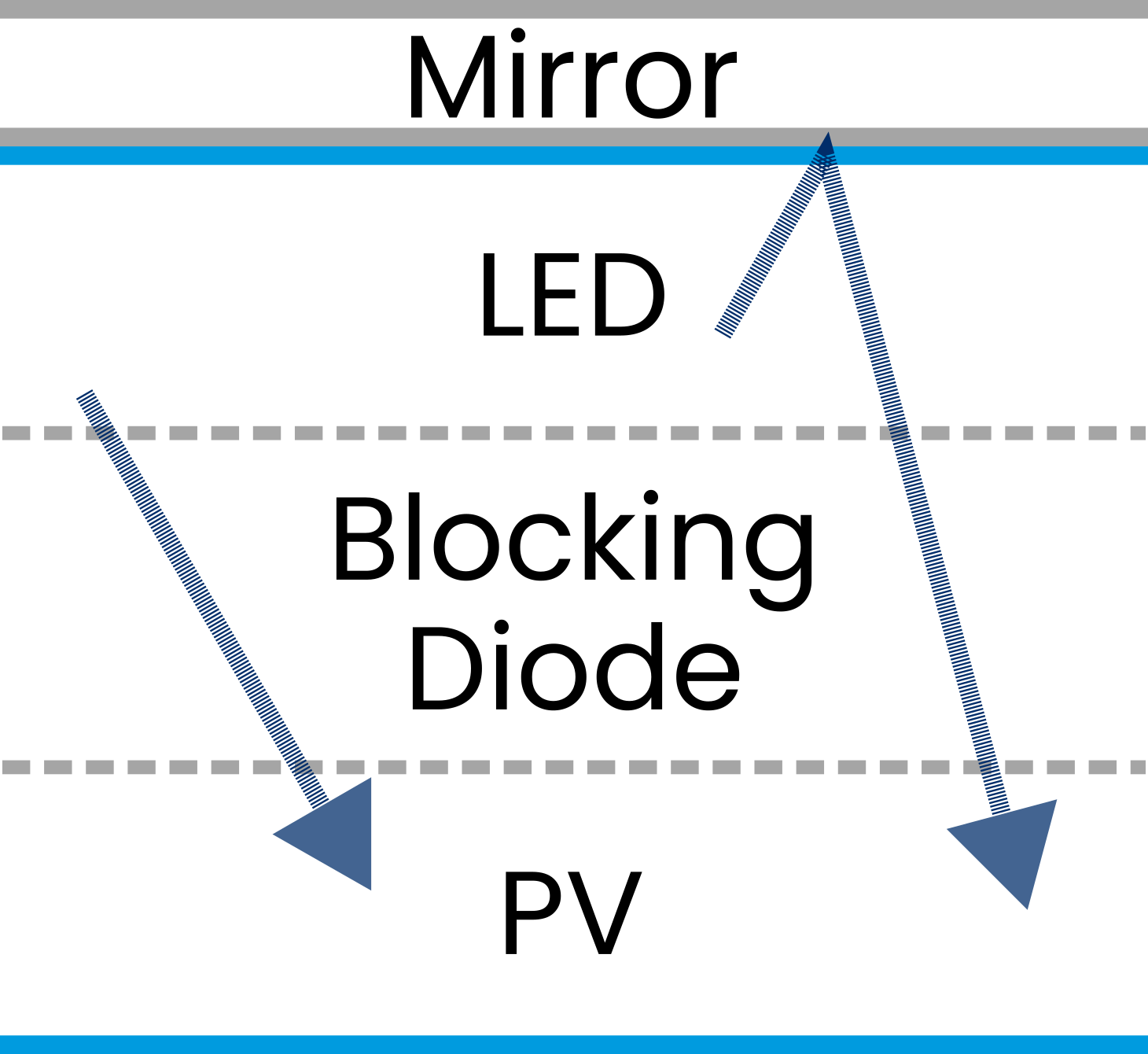
In a conventional optocoupler the emitter and receiver are separate dies, assembled and aligned in a package and coupled across an optical gap — built to pass a signal, not to deliver power. The MLOC eliminates the gap: photovoltaic cell, semiconductor blocking diodes, and LED are grown together as a single GaAs crystal stack, with an integrated mirror that folds the LED's upward emission back down into the PV cell. The blocking diodes pass light but block current, isolating the PV cell from the LED at the tens-of-volts level a power-management device needs — this is a power-transfer chip, not a kilovolt safety isolator. No die-to-die interface, no alignment loss: the dominant loss paths of a discrete pair are simply gone.
The payoff is LED-to-PV power-conversion efficiency above 52% — more than 25 times the percent-or-two a conventional optocoupler can move — with an unamplified current transfer ratio above 72% per LED/PV pair. That margin turns "recycle the dropout energy as light" from a laboratory curiosity into a regulator typically 1.2× to more than 2× as efficient as a conventional LDO, with the largest gains on large step-downs, and it is what makes efficient switching-free boost possible at all. The chips are built on the same mature, high-volume III-V production lines as commodity high-brightness LEDs — no exotic processes, no precision optical assembly.
The optocoupler is the enabling chip — but a chip alone is not a regulator. Three granted U.S. patents cover the invention at every layer: the monolithic device, the buck topology that recycles dropout energy, and the founding patent on photon-coupled regulation itself.
The monolithic optocoupler
The device patent: LED, blocking diodes, and photovoltaic cell grown as one monolithic GaAs stack, with an integrated mirror that redirects emission into the PV cell — the structure that makes optocoupler power transfer efficient.
The efficient buck
The step-down topology: the LED string shares the input-to-output voltage drop with the regulator's pass device, and the photovoltaic section feeds the recovered current forward to the output — the circuit at work in every buck ELR.
The founding patent
The 2018 priority filing that started it all: a linear regulator that moves power on photons, covering efficient step-down of large voltage drops and — by stacking photovoltaic voltage above the input rail — DC up-conversion with no switching, the basis of every switching-free boost ELR.
What it means in practice
Every number below is published — in the white paper, an application note, or a product document.
60–85% buck conversion
Buck ELRs operate at 1.2× to >2× conventional-LDO efficiency depending on the voltage step; the BT29 boosts at >65% peak with zero switching.
<1 µV RMS configurations
The BK30 series reaches sub-microvolt RMS output noise (10 Hz–100 kHz) with PSRR above 120 dB near 1 kHz — linear-regulator power integrity at far higher efficiency.
Radiation-tolerant: 200 krad(Si)
All four families are rated radiation-tolerant to 200 krad(Si), and the BK19 is built on a QML-V radiation-hardness-assured LDO core. Behind the rating is a full characterization campaign: cobalt-60 TID with published output-voltage shifts under 1.5%, destructive single-event-effects testing, and proton, electron, and neutron irradiation, plus MIL-STD-883-style life and thermal-cycle screening — reports available to customers.
Validated on orbit
Polaris ELRs launched to the International Space Station in October 2025 aboard JAXA's HTV-X1 on the Aegis Aerospace MISSE-21 platform. The flight-heritage experiment has been operating continuously since January 8, 2026 — thousands of hours logged and counting — with devices performing as expected against a ground-control twin.
Proven LDO cores, enhanced
Polaris doesn't ask you to bet on an unproven regulator core. Each ELR family is built around an industry-standard LDO that design teams already qualify and trust — the QML-V radiation-hardness-assured RH1965 (BK19), the high-current MIC29152 (BK29, BT29), and the ultra-low-noise LT3045 (BK30). The optocouplers enhance the core's efficiency; its regulation behavior, protection features, and noise pedigree carry straight through.
The technology is documented in a technical white paper developed with The Ohio State University and supported by Texas Instruments, whose team supplied the radiation-hardness-assured linear regulators behind the paper's rad-hard ELR demonstration. Our application notes carry the same proof-first approach into practice: complete, measured reference designs — from all-linear Li-ion charging to adaptive multi-source power — built from ELRs and readily available commercial parts.
Where clean power is the bottleneck
Noise-sensitive DC power is the high-performance slice of the roughly $14B global DC-DC converter market — a $1.5B+ segment today, and the one where engineers accept a power-loss premium because nothing else meets the noise spec. The ELR enters where that pain is sharpest, and is expanding from there.
Space, defense & precision instrumentation
SmallSat and spacecraft power, RF and microwave front-ends, scientific and medical instrumentation — mission-critical systems where signal fidelity and SWaP are hard constraints, not preferences. The ELR is already flying on the ISS, with first commercial shipments in August 2025.
Why ELR wins: the noise spec without the efficiency penalty
High-speed data, automotive & 5G/6G
Data-center interconnects and retimed links, automotive LiDAR and radar, radio units, and industrial sensing: high-volume systems where SerDes jitter budgets, EMC-qualification risk, and board space leave no room for switching noise or a two-stage filter chain.
Why ELR wins: switching-class efficiency, zero EMC surprises
Quantum, photonics & chiplets
Quantum systems, free-space optical communications, and chiplet-based heterogeneous packages — where power increasingly must be delivered inside the package, with no room for an inductor and no tolerance for EMI. A monolithic optocoupler is a natural fit for chiplet-scale integration.
Why ELR wins: inductor-free power that integrates where switchers can't
Spotlight: the high-speed interconnect rail
Inside an optical module — or an active electrical cable doing the same retiming job in copper — the 3.3 V cage supply has to step down to the lower logic rails that feed clock-and-data recovery, retiming, and jitter attenuation — in millimeters of board space, against a hard thermal ceiling, for circuits whose jitter budgets are measured in femtoseconds. Today that means either burning the difference in an LDO or filtering a switcher out of the most noise-sensitive signal path in the system. An ELR does the same step-down at switching-class efficiency with no switching edge at all: less heat in the cage, no spurs near the eye, nothing to filter.
The multiplication is the point. An AI cluster runs on the order of six optical links per GPU — before counting the retimed copper (AECs) filling the shorter hops; a 72-GPU rack carries hundreds of them; a 100,000-GPU campus approaches six hundred thousand — and every link terminates in CDR silicon that needs quiet rails, at both ends. With data-center operators committing more than half a trillion dollars a year to new AI capacity, the cleanest rail in the rack is no longer a niche.
Wherever power integrity limits performance
Our work in noise-sensitive power began in aerospace, defense, and precision instrumentation — where the ELR is flying today. The same physics, and the same proven-core philosophy, scale to the markets that come next.
Ready to design it in?
Request evaluation samples, detailed datasheets, and SPICE models — an engineer answers, not a sales funnel.